Scrap Antenna Project - Ethernet Cantenna
The Challenge
Callum McCormick, M0MCX of DX Commander posted a challenge on his YouTube channel to create an “emergency” 20m vertical antenna out of scrap. As an amateur radio operator who is pretty new to HF, after watching his video I knew immediately I wanted to build a contest entry and quickly formulated an idea.
Design Requirements
I encourage you to watch the video, but I summarized the design requirements for myself as follows:
- Vertical antenna (or variants, such as inverted L or linear loaded) for the 20 meter band (14 to 14.35 Mhz in the USA)
- Constructed primarily out of scrap (parts used must be lying around/left over, not acquired new for this purpose)
- No RF parts except for coax (RF connector allowed at radio end)
- Not more than 2 wavelengths of radials
- No more than 4 radials together in a bundle, with some type of fast connectors for each.
- Must be able to be disassembled and placed in a box or bag, to be deployed when needed in an “emergency.” This includes a quick disconnect for the coax, which should not be an RF connector. (No SO-239 or BNC connectors, for instance.) Some effort should be made to make it waterproof so water doesn’t get into the coaxial cable.
Submission Requirements
Submissions had to be emailed with horizontally oriented pictures, “a couple hundred words” of explanation (this is obviously not the brief summary), and results/conclusion by December 20, 2022.
Parts Selection
Inspired by (1) dad jokes about “Wireless Ethernet” and (2) two cans connected by a string, I decided to construct my antenna with Ethernet cable and a small soup can as its main components. I still think it would be amusing to talk to someone with a similarly designed antenna, so it would be the ham radio evolution of two cans connected by a wire with help from the ionosphere.
Parts included the following:
- One 1/4 wavelength long bit of CAT6 cable (a bit under 18 ft), of which I had plenty left over from when I ran Ethernet cable in our home. One conductor would be the vertical and the remaining ones would be used for the radials. I kept it on the long side to allow for mishaps.
- One small tomato soup can, to serve as a ground plane. I believe it was a 10.75 oz can.
- One wire coat hanger, with the enamel burned off, which serves as ground stakes to hold the assembly in place at ground level
- A bit of plastic cut from a Country Crock plant oil spread container lid, to serve as a top cover for the assembly and to keep the vertical insulated and away from the can
- Wago 221 connectors to connect the radials (3 position connectors) and the coax (2 position connectors).
- Crimp ferrules to bundle the radials together and crimp the braid on the coax
- Ring connectors and short lengths of hookup wire to connect the applicable Wago connectors to the can
- Sheet metal screws to secure the ring terminals and wire hanger to the can
- One small machine screw and nut to secure a ring terminal/hookup wire/Wago assembly for the coax braid
- Four pop rivets, to secure the plastic cover to the top of the can
- A bit of heat shrink, electrical tape, and caulk
Construction & Deployment
Ethernet cable
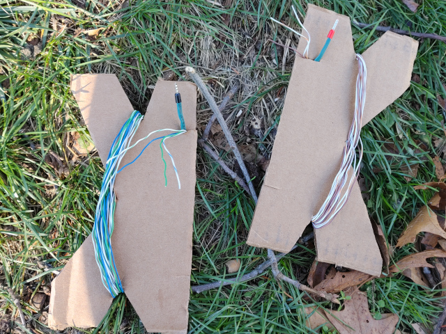
Probably the hardest part of this build was unwinding the twisted pairs of the ethernet cable. I used the orange conductor of the 1/4 wavelength of Ethernet cable as the vertical element, primarily so it could be seen more readily in pictures. The remaining seven conductors were cut into three pieces each, making them about 1/12th of a wavelength. I made three bundles of 3, and three bundles of 4, held together by a bit of heat shrink and a crimp ferrule at one end. I kept related conductors together for no particular reason other than aesthetics, so there were 3 bundles of green, white green, blue, and white blue, and 3 bundles of brown, white brown, and white orange. This means I have fairly short radials, and only 1.75 wavelengths of them in total, but I wanted to limit myself to just the one 1/4 wavelength of Ethernet cable. Also, as the wire hanger and soup can are also techically part of the ground system, I didn’t want to go right up against the 2 wavelengths limit and appear to be cheating. One of each radial type is shown below, with wire winders I made from scrap cardboard to keep them organized until I was ready to go outside and deploy the system on a day that the weather cooperated.
The Can
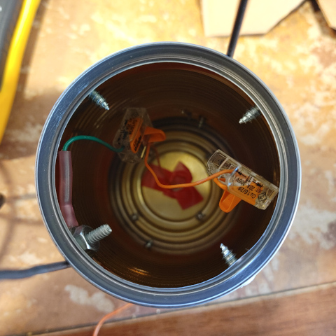
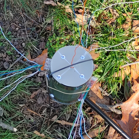
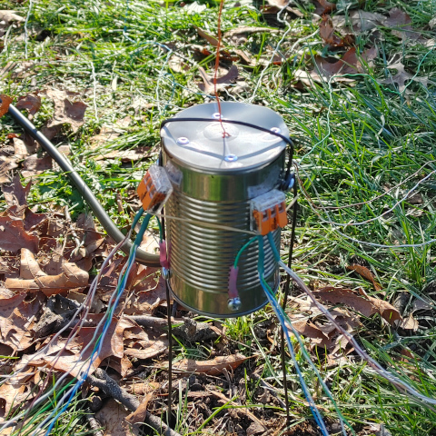
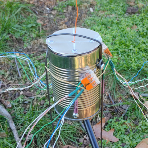
To prepare the soup can, I drilled a large hole in the top, and insulated it with electrical tape to prevent the vertical element from rubbing against it and shorting out. I also drilled pilot holes for the sheet metal screws, and holes in the top for the pop rivets. I cut a bit of plastic from the Country Crock container lid and drilled a few holes near the center. With a little bit of caulk around the bottom of the plastic cover to keep water out of the inside of the can, I pop riveted in place on top of the can. I weaved the vertical element through the three center holes for strain relief. I secured the short hookup wire with ring terminals to the can, and clipped the Wago connectors to them as shown. With the wire coat hanger bent straight and the enamel burnt off, I bent it in the shape of a large staple with circular bends in each side for securing to the can with sheet metal screws. The finished product is shown below.
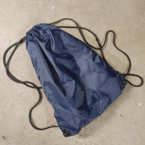
To pack it away, all the former CAT6 wire can be wound up and put into the can (albeit with a little sticking out) or wound around the wire hanger “stakes,” but in doing so I found it easy for the wires to get tangled. I think in the future I will wind each bundle separately and keep the whole thing together in a promotional drawstring bag freebie that we had lying around the house, as shown packed away below. Not shown is the logo from the graduate department of a University that shall not be named, that is found on the other side of the bag. 😆
Deployment
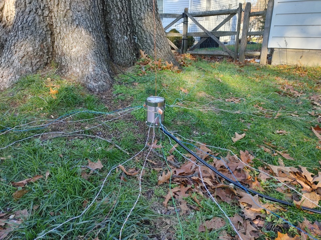
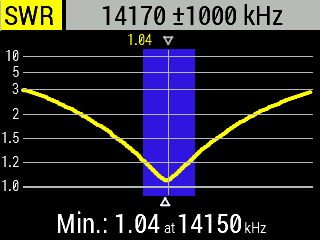
Unfortunately, days that were not raining and my days off from work did not coincide until very close to the deadline. Thankfully, I was able to complete most of the construction inside. On testing day, I had already thrown some inexpensive paracord up in a large oak tree in our backyard, so I stuck the cantenna in the ground, ran the vertical up the tree, and attached & spread out the radials. I put a rubber band around the can as shown just for a little strain relief on the short wires while I was manipulating the radials. Since I left a little wiggle room, the antenna was shown on my Rig Expert antenna analyzer to be a little long, so I trimmed it to size, and much to my surprise I was able to achieve an SWR of 1.04 right in the middle of the 20 meter band, and about 1.2 near the band edges!
I left it undisturbed for a few weeks, and despite rainy weather the inside of the can seems to have stayed dry as I had hoped.
Results
Using my Xiegu X6100 set to 10 Watts from my home in New Jersey (FN20), I made voice contacts with five stations in just over fifteen minutes. All of these were POTA activators, so I included their parks in the log below:
| Callsign | State | Park | Grid | Distance | Freq Mhz | Rpt Rcvd | Rpt Sent | Time UTC |
|---|---|---|---|---|---|---|---|---|
| KU8T | IN | K-4208 | EN70 | 910 km (565 mi) | 14.264 | 59 | 59 | 19:24 |
| KK1LL | NC | K-6853 | EM85 | 858 km (533 mi) | 14.271 | 55 | 59 | 19:29 |
| KC0ECQ | MO | K-6503 | EM48 | 1351 km (839 mi) | 14.291 | 55 | 57 | 19:35 |
| KG9JP | WI | K-4306 | EN54 | 1229 km (763 mi) | 14.304 | 53 | 55 | 19:37 |
| KO4WTG | GA | K-0662 | EM74 | 1109 km (689 mi) | 14.320 | 55 | 54 | 19:40 |
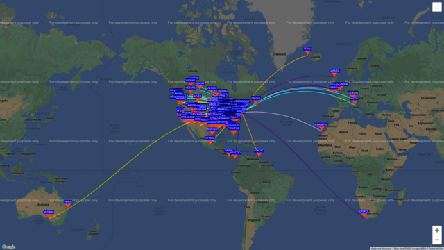
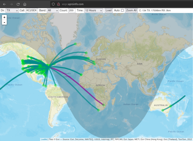
I then ran WSPR at 5 Watts, and got the following results. I was heard all the way in Australia, about 17000 km (10,000 mi) away!
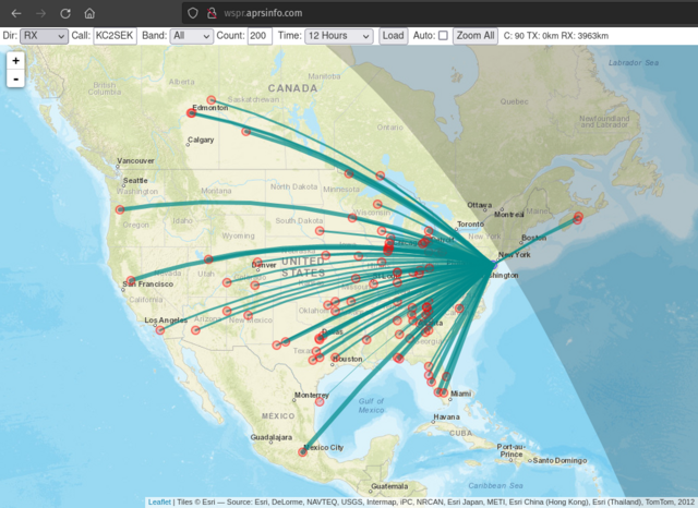
The stations I was able to receive during this short WSPR test were limited to North America, which I believe might be partially due to the radials being short in length and few in number. The graph from wspr.aprsinfo.com with the red dots shows stations I heard, and the one with the green dots shows stations that heard me. The latter should match the first map from wsprnet.org. One of the judges commented that the antenna appeared to be a little directional. If I had to guess, I’d attribute the northern issue to possibly placing the radials poorly in that direction, especially since that is where the giant oak tree is. I’ll have to do some more thorough testing when I have more time and I’m not chasing daylight.
Judging
Callum said he was hoping for about ten entries, but received almost fifty! My antenna is evaluated about one hour and one minute into the first of the two judging videos, and you can skip directly to me by clicking here. That said, all of the designs are interesting on their own merits and are worth reviewing. It was fun to see what everyone else came up with.
The five judges were allowed to liberally apply their own criteria to two categories, each of which were awarded a maximum of 10 points: (1) presentation and understanding the assignment, and (2) execution. A poll of the chat room could award up to an additional 8 points. I scored a respectable 88 points out of a maximum of 108, and tied for 17th by my count. I found the comments to be very positive overall and I was quite pleased. One participant in the chat even compared mine to the eventual winner. Although I hadn’t used a bean can of the British staple “Heinz Beanz” variety, I really liked Mike M0MSN referring to it as a “Heinz-brid” antenna. 😆
Part 1 (Includes this antenna!)
Part 2
Changes
I really like this concept, and I’m definitely going to use this antenna in the future. Now that the contest is over, however, I’ve made some minor changes for myself:
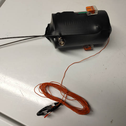
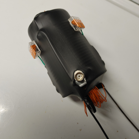
- Added a BNC connector to the can. This is the only change I think I’ll make that completely violates the original design brief, but I can now use any coax available with the required connectors attached or with appropriate adapters if necessary, rather than just the length of coax that I prepared for this purpose.
- Added a large heat shrink sleeve (about 3 inch diameter circle) covering the can to keep it neat and prevent corrosion. Yes, I had to acquire this, so it’s not exactly scrap. The only problem was that I melted the plant oil spread plastic cover a little with the heat gun. Oops. This is addressed with another change (last bullet point), so it’s not a problem.
- Hot glued the Wago connectors to the side of the can/heat shrink so they’re not flapping around.
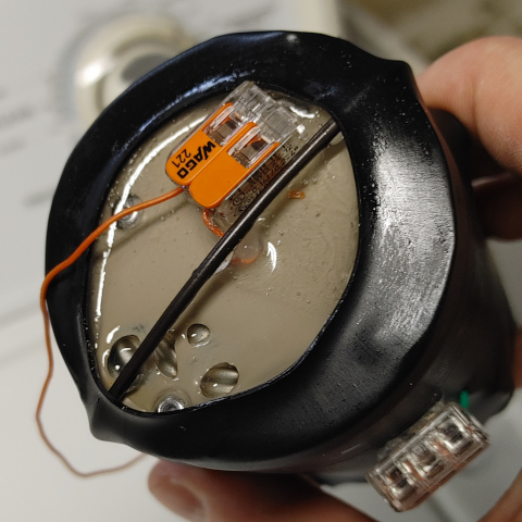
- Used an epoxy resin (J-B Weld ClearWeld) to seal off the top, and added another Wago secured by the epoxy. This way the vertical element can be swapped out for another, and the Wago connector cannot be pulled off by tension from the vertical.
Future Updates
Using this updated Cantenna base, I can now switch to different verticals and radials for different bands or configurations. I could even potentially allow for multiple vertical elements to create a DX CANmander. 😁 Also, if I find more evidence of somewhat worse reception than expected I can consider changing both the length and number of radials, and making each bundle of radials identical at that time.
Conclusion
All in all, this was a fun and rewarding project. I encourage anyone interested to give it a try with similar design parameters and share their experience. Questions and comments can be emailed to me at my callsign AT arrl.net. Thanks for stopping by!
73,
Matt KC2SEK
